
This section will describe the Edit Geometry area and how it is used to edit external references, named points, and connector references. More information on these types may be found on the External References and Connector References pages. To start editing an element of these types, double-click it in the Product View.
Edit External Reference

This section will vary depending on whether the external reference being edited is placed on the product or an option.
- File URI: A reference to a model within the Symbols Directory or any of its subdirectories. The user can enter a location manually in this field, or press ‘…’ on the right side to open the file browser. If the model is unreadable or unreachable, the text in this field will appear red.
- Usage Type: This indicates how the model is used. 3DView will cause the symbol to use the model in the 3D view of a drawing. PlanView will cause the symbol to use the model in the 2D view of a drawing. 3DAndPlanView will cause the symbol to use the model in both 3D and 2D views.
- Preview File URI: This field is largely obsolete, and primarily exists for working with older catalogues. It is used to specify an image that should be used as a preview for the product or the option. The user may enter a location manually in this field, or press ‘…’ on the right side to open the file browser. If the image is unreadable or unreachable, the text in this field will appear red. Note that the current preferred method for assigning preview images is via the Preview Images tab.
- Overlay Line Type: This option, when set, changes the 2D line type of an external reference to a dashed line, and makes the line always show on top.
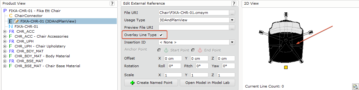
- Insertion ID: The meaning of this field depends on whether the user is editing an external reference on the product or an option. On a product, this field is used to create insertion IDs that options may reference. On an option, this field is used to reference an insertion ID on a product. In either case, an insertion ID may be entered into this field by double-clicking on it and then typing in a value. Or the user may click the down-arrow on the right side to open a list of previously used insertion IDs.
In the case of an external reference placed on an option, this area will refresh to show the Named Point control if an insertion ID is chosen, or the normal placement controls if no insertion ID is chosen. - Anchor Points: Measure parameters can be applied to external references to allow the model to stretch on the measure parameter axis.
- Named Point: Only applies to external references placed on an option. This field makes reference to a named point on an external reference on a product. A named point may be referenced by selecting an existing named point from the drop-down list, or by double-clicking in the field and entering a named point by name.
- Offset: These fields represent the offset of the model from its defined zero point. Note that in CET, X (horizontal) and Y (vertical) are the 2D planes, and Z is the elevation in the 3D. Distances may be entered into the fields manually. The distance unit will match the unit set for the catalogue on the Project Directory tab.
- Rotation: The degree by which the model is rotated about the rotation vector. Values may be entered manually. The value is measured in degrees.
- Scale: These fields describe the magnitude by which the model is shrunken or stretched in three directions. Values may be entered manually. There are no units.
- Create Named Point: Only applies to external references placed on a product. This button will create a new named point on the external reference. Once pressed, the creator will append an empty named point to the external reference, and the Edit Geometry area will update to allow editing of it.
- Open Model in Model Lab: This button will open the current model in the Model Lab. Note that if changes are made to the model, they will not be automatically reflected in the 3D and 2D views. Press Refresh All, or press F5 key on the keyboard, to refresh the drawing views.
Edit Named Point
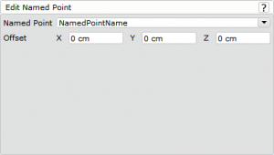
When a named point is added to an external reference via the Create Named Point button, it can be edited by double-clicking it in the Product View. At that time, the Edit Geometry area will update to allow editing.
- Named Point: This field represents the name of the named point. The user can select an existing name by clicking the downward-facing arrow and selecting a name from the list. Alternatively, a new name can be entered manually by double-clicking in the field, then typing in a value.
- Offset: These fields represent the location of the named point. Values can be entered manually. The distance unit is the same unit as specified on the Project Directory tab.
Edit Connector Reference
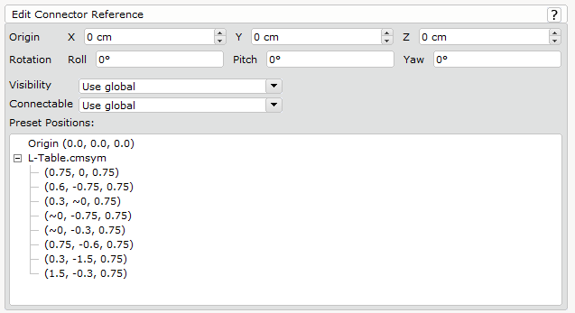
Symbols make use of connectors by way of connector references. A connector describes the behavior of the connection, and connector reference refers to that particular connector in the symbol with options to manipulate it on the symbol level.
- Origin: These fields describe the location of the connector. Values can be entered manually. The distance unit is the same unit as specified on the Project Directory tab.
- Rotation: The degree by which the model is rotated about the rotation vector. Values may be entered manually. The value is measured in degrees.
- Visibility : This is a list of options available to define how the connector should be visible. Connectors set as attach will always be invisible. This option will override the settings on the Edit Global section and will only apply on the connector that is defined on the current product.
- Use global : This option will use the option defined in the Edit Global section.
- Always visible : This option will define the snap connector to be always visible.
- Never visible : This option will define the snap connector to be invisible
- Visible only for main product : This option will define the snap connector to be visible, provided that the product the snap connector belongs to is the main product.
- Visible only for additional product : This option will define the snap connector to be visible, provided that the product the snap connector belongs to is the additional product of a main product.
- Connectable : This is a list of options to define the type of the connector this connector can snap to. This option will override the settings on the Edit Global section and will only apply on the connector that is defined on the current product.
- Use global : This option will use the option defined in the Edit Global section.
- Always connectable : The connector will be able to connect to another connector as long as the Attach rule matches.
- Only for main product : The connector will only be able to connect to another connector provided the Attach rules matches and the product this connector is defined on is a Main Product and the attach's product is also a Main Product.
- Only for additional product : The connector will only be able to connect to another connector provided the Attach rule matches and the product of this connector is defined on is an Additional Product and the attach's product is also an Additional Product.
- Preset Positions: Some models have points embedded into their files, referred to as Nodes. This is a list of all of such points that have been found in the models that are currently being referenced by the product. When the user first clicks an item in the list, the 3D View will update, adding blue dots to the preview to show the different points available. If a point is selected from the list, that point will appear in a darker blue, to show it’s location on the symbol. If a point in the list is double-clicked, the origin of the connector reference will be set to that point. This can only be done by plotting the “points” in a DWG file in CAD tool.
Comments
0 comments
Please sign in to leave a comment.